Disclosure: This post contains affiliate links and I will be compensated if you make a purchase after clicking through my links. Learn More
Flux core welding is popular among professionals and hobbyists. It works well for building structures, repairing machinery, or creating art from metal. One of the most important factors in getting strong welds is choosing the right amperage. The flux core welding amperage chart is a practical tool. It helps you set the correct current for your wire, material, and project.
Many people guess the settings, which leads to weak joints, too much spatter, or burned-through metal. The chart removes guesswork. It gives you reliable numbers that improve your work and reduce mistakes. This article explains how the flux core welding amperage chart works, why it matters, and how to use it.
You’ll also see real examples, tips, and tables for quick reference.
What Is Flux Core Welding?
Flux core welding, also called FCAW (Flux Cored Arc Welding), uses a special wire. This wire has a hollow center filled with flux. The flux creates a shield around the weld, so you don’t need a separate gas tank in most cases. People use flux core welding for outdoor jobs, repairs, thick steel, and places where wind would blow away shielding gas.
There are two types:
- Self-shielded flux core wire (FCAW-S): Does not need extra shielding gas.
- Gas-shielded flux core wire (FCAW-G): Uses both flux and an external gas.
Most home and field welders use the self-shielded type. It’s simple and portable. The amperage chart works for both types, but this article focuses on self-shielded wires.
Why Is Flux Core Welding So Popular?
Flux core welding is popular for several reasons. First, it works well outdoors, where wind can be a big problem for gas-shielded welding. The flux inside the wire protects the weld, even in windy conditions. Second, the setup is easy.
You do not need a gas cylinder, regulator, or hoses. This makes the whole kit lighter and more portable. Third, flux core welding is very forgiving on dirty or slightly rusty metal. The flux helps remove some surface impurities, so you can weld without perfect cleaning.
This is helpful for repair jobs or working on older equipment.
Another reason is the ability to weld thicker metal with small machines. Many 120V welders can handle thick steel using flux core wire. This gives you more options as a beginner or hobbyist. Finally, flux core wires are often easier to find and less sensitive to storage conditions than solid MIG wires, which can rust quickly if left in humid air.
Common Uses For Flux Core Welding
Flux core welding is used in many industries and DIY projects. You will find it in construction for making building frames, in auto repair shops fixing car frames, and in farm equipment maintenance. Artists also use flux core for making metal sculptures, gates, and furniture.
Because it works on thicker steel, many home projects like building trailers or fences use flux core welding.
Why Amperage Matters In Flux Core Welding
Amperage is the amount of electric current flowing through the wire and metal. It controls how deep the weld melts into the base metal. If amperage is too low, the weld sits on the surface and is weak. If it’s too high, the metal burns through or warps.
Right amperage gives:
- Good penetration (the weld joins deep into the metal)
- Smooth bead (the weld looks neat)
- Less spatter (fewer metal droplets fly off)
- Stronger joints (the weld holds under stress)
Wrong amperage causes:
- Porosity (holes in the weld from trapped gas)
- Cracking
- Burn-through
- Poor fusion (the weld doesn’t bond well)
The chart helps you avoid these problems.
How Amperage Affects Weld Quality
Proper amperage does more than just melt the metal. It also shapes the weld bead and controls how the weld cools. If the amperage is too low, the wire piles up on the surface, creating a bead that looks tall and narrow.
This bead will not hold under stress. On the other hand, if amperage is too high, the bead becomes flat or even sinks below the surface, creating a weak spot. You may also see the edges of the weld (called undercut) become too thin, which is a common failure point.
An often-missed detail is that correct amperage reduces the need for grinding and rework. When you use the right settings, your weld will require less cleaning, saving time and materials. Another benefit is less wear on your welding gun and machine, as you avoid overheating and damaging parts by using extreme settings.
How Amperage Relates To Other Settings
Amperage does not work alone. It interacts with voltage and wire feed speed. If you change one, you often need to adjust the others. For example, higher amperage usually means you need more voltage for a stable arc, and the wire feed speed must match so the weld is neither starved nor overloaded with wire.
Understanding this relationship helps you get the most out of the amperage chart.
How The Flux Core Welding Amperage Chart Works
The chart matches three main factors:
- Wire diameter (thickness of the welding wire)
- Metal thickness (how thick your workpiece is)
- Recommended amperage range
Other factors include wire type and welding position, but these three are the most important.
Here’s a common sample:
| Wire Diameter | Metal Thickness | Amperage Range | Voltage Range | Wire Feed Speed |
|---|---|---|---|---|
| 0.030″ (0.8 mm) | 18–20 ga (1.0–1.2 mm) | 60–90 A | 16–18 V | 250–350 ipm |
| 0.035″ (0.9 mm) | 16–14 ga (1.6–2.0 mm) | 90–140 A | 17–20 V | 300–400 ipm |
| 0.045″ (1.2 mm) | 10 ga–1/4″ (2.5–6.4 mm) | 140–200 A | 19–22 V | 350–500 ipm |
These are general numbers. Check your wire and machine for exact values.
Why Use A Range Instead Of A Fixed Number?
Welding charts give a range for each setting because real-world conditions change. Metal composition, air temperature, and even the angle of your welding gun can affect the result. A fixed number would not work well for every project. A range lets you start safely and adjust as needed.
For example, older steel or painted surfaces may need a little more or less amperage than new, clean steel. The range also covers different welding positions, as vertical and overhead welds require slightly different settings.
How To Read The Chart Efficiently
Many beginners struggle to find the right row in the chart. Always start by matching your wire size first, then move across to your metal thickness. Only after these two match should you look at the suggested amperage, voltage, and wire feed speed.
If your exact thickness isn’t shown, use the next thicker setting as a starting point, but make a test weld before starting your project.
Key Factors That Affect Amperage Settings
Understanding these will help you use the chart effectively.
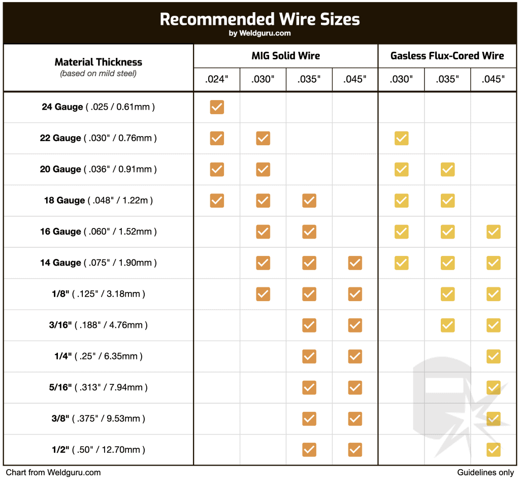
1. Wire Diameter
Thicker wires need more amperage. Thinner wires melt at lower currents. Most home welders use 0. 030″ (0. 8 mm) or 0. 035″ (0. 9 mm) wires.
Choosing The Right Wire Diameter
Choosing the right wire for your project is important. For thin sheet metal, 0. 030″ wire works well, as it gives better control and lower heat. For medium-thick metal (like car frames or tool repairs), 0. 035″ is the common choice.
For thick steel plates or farm equipment, 0. 045″ wire allows more amperage and faster welding. Using a wire that is too thick for your welder can overload the machine, while a wire that is too thin will make welding thick metal slow and frustrating.
2. Metal Thickness
Thin metal burns through easily. Use lower amperage. Thick metal needs more heat (higher amperage) to melt properly. Always match your settings to the thickest part of your workpiece.
Measuring Metal Thickness
If you are not sure how thick your metal is, use a caliper or a sheet metal gauge tool. Many welders make mistakes by guessing, which often leads to poor welds. For example, car body panels are often 18–20 gauge, which is about 1.
0–1. 2 mm thick, while trailer frames might be 1/8″ (3. 2 mm) or thicker.
3. Welding Position
Flat welds can use higher amperage than vertical or overhead. For vertical or overhead, lower the amperage about 10–15% to prevent the weld from dripping.
Adjusting For Position
It’s easy to forget to change your settings when moving from flat to vertical or overhead. For example, if you welded a flat joint at 120 amps, drop to around 105 amps for a vertical weld. This small change prevents the molten metal from sagging or falling out of the joint.
If you notice the weld pool is hard to control in overhead or vertical, check your amperage first.
4. Wire Feed Speed
Wire feed speed (WFS) controls how much wire enters the weld. Higher WFS usually means higher amperage, but if it’s too fast, it causes spatter and poor fusion. The chart often includes WFS for reference.
Balancing Wire Feed Speed
Think of wire feed speed as the “fuel rate” for your weld. If you feed wire too slowly, the arc is weak and the weld does not fill the joint. If you go too fast, the wire “pushes” into the weld puddle and causes spatter.
A good practice is to set your amperage first, then adjust wire feed until the arc sounds steady and the bead is smooth.
5. Machine Capability
Some machines can’t provide very high or very low amperage. Always stay within the safe limits for your welder.
Knowing Your Welder’s Limits
Check your machine’s manual for its amperage range. Small 120V welders often max out around 140 amps, while larger 240V units go much higher. Never try to push your machine beyond its safe range. It can damage the welder or produce poor welds.
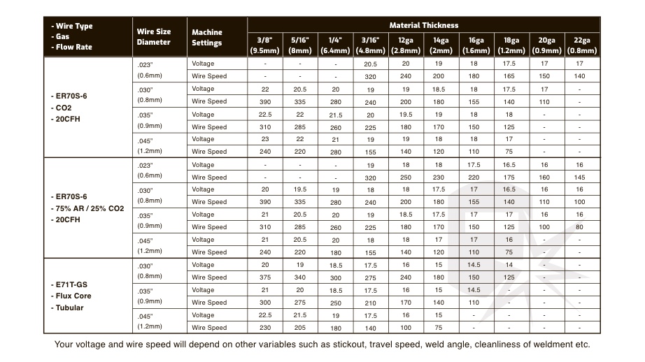
Sample Flux Core Welding Amperage Chart (expanded)
Here’s a more detailed chart for reference.
| Wire Size | Material Thickness | Amperage | Voltage | Wire Feed Speed (ipm) | Welding Position |
|---|---|---|---|---|---|
| 0.030″ | 18 ga (1.2 mm) | 60–80 | 16–18 | 250–300 | Flat |
| 0.030″ | 14 ga (2.0 mm) | 80–100 | 17–19 | 300–350 | Flat/Horizontal |
| 0.035″ | 1/8″ (3.2 mm) | 110–140 | 18–20 | 350–400 | Flat |
| 0.045″ | 1/4″ (6.4 mm) | 170–200 | 21–23 | 400–500 | Flat |
| 0.045″ | 1/4″ (6.4 mm) | 150–170 | 20–22 | 350–450 | Vertical/Overhead |
Non-obvious insight: Charts usually give a range. Start in the middle of the range, then adjust based on your weld bead and sound.
How To Use This Chart In Practice
Let’s say you have a 0. 035″ wire and 1/8″ steel. The chart says 110–140 amps, 18–20 volts. Start at 125 amps and 19 volts. Make a short test weld. Check if the bead shape is good and the weld penetrates but does not burn through.
Adjust in small steps if needed.
How To Use The Amperage Chart Step-by-step
- Pick your wire size. Check your wire spool or machine label.
- Measure your metal. Use a caliper or sheet metal gauge.
- Find the right row in the chart. Match wire and metal thickness.
- Set amperage and voltage. Use the chart’s range.
- Adjust wire feed speed. Set as suggested.
- Test on scrap metal. Make a short weld. Check bead shape, penetration, and spatter.
- Fine-tune if needed. Raise or lower settings in small steps.
Common mistake: Many people skip the test weld. Always make a test bead before starting on your final work.
Why Test Welds Matter
Test welds help you spot problems before you start your main project. A test bead can show if you have the right heat, if the wire is feeding smoothly, and if the weld pool is easy to control. If you see too much spatter or the bead is sitting too high, adjust your settings.
Even experienced welders make test welds when changing materials or positions.
Adjusting After The Test
If your first test weld is not perfect, change only one setting at a time. If you adjust both amperage and wire feed speed together, you may not know which change made the difference. Small changes (5 amps or 10 ipm) can make a big difference in weld quality.
Real-world Examples
Example 1: Repairing A 1/8″ Steel Bracket
- Wire: 0.035″ flux core
- Metal thickness: 1/8″ (3.2 mm)
- Chart range: 110–140 amps, 18–20 volts
Set your welder to 125 amps and 19 volts. Do a test weld. If the bead is flat and smooth, continue. If it sits on the surface, raise the amps. If it burns through, lower the amps.
What To Watch For
If the bracket is painted or rusty, clean the area before welding. If the bracket is thick, but you cannot reach 140 amps, consider making two passes: a root pass to join the metal and a cover pass to build up the weld.
Example 2: Welding Thin Sheet Metal (18 Gauge)
- Wire: 0.030″ flux core
- Metal thickness: 18 ga (1.2 mm)
- Chart range: 60–80 amps, 16–18 volts
Start at 70 amps and 17 volts. Use a faster travel speed to avoid burn-through. Reduce voltage if you get too much spatter.
Special Tip
Thin metal can warp from heat. Use short welds (“stitch welding”) instead of one long bead. Move around the panel to spread the heat and keep the metal flat.
Example 3: Building A Heavy Duty Gate (1/4″ Steel)
- Wire: 0.045″ flux core
- Metal thickness: 1/4″ (6.4 mm)
- Chart range: 170–200 amps, 21–23 volts
Set at 185 amps and 22 volts. If your machine cannot reach 200 amps, make multiple weld passes.
Extra Detail
Heavy gates need strong, deep welds. If you see the weld bead sitting high or not joining both pieces, increase amperage. For outdoor gates, make sure the joint is clean and dry to avoid porosity.
How To Read And Interpret Amperage Charts
Charts are not always the same. Some show only wire size and amps. Others add voltage and wire feed speed. If a table is missing a value, use the closest match and adjust based on your weld results.
Tip: The amperage often rises as wire feed speed increases. If your welder uses wire feed speed as the main dial, start at the center of the suggested range.
Here’s a simple comparison:
| Wire Size | Amperage Only | Amperage + Voltage + WFS |
|---|---|---|
| 0.035″ | 90–140 A | 90–140 A, 17–20 V, 300–400 ipm |
| 0.045″ | 140–200 A | 140–200 A, 19–22 V, 350–500 ipm |
If your chart only gives amperage, use the middle of the range and adjust voltage and WFS for a stable arc.
Decoding Manufacturer Charts
Different brands may use different terms or units. “ipm” means inches per minute for wire feed. Amperage may be shown as “A” or “amps. ” If you see settings in metric, use a conversion calculator. Always double-check your wire size, as some wires from overseas are 0.
9 mm instead of 0. 035″.
Tips For Beginners Using Amperage Charts
- Always check wire and machine labels. Not all wires use the same settings.
- Make test welds on similar scrap.
- Change one setting at a time. If the weld is wrong, don’t change everything at once.
- Listen to the arc. A steady “hissing” sound is good. Loud popping means wrong settings.
- Keep the workpiece clean. Rust or paint can affect how the weld forms.
- Watch the weld pool. If it’s too hot or too cold, adjust amperage by 5–10 amps.
Non-obvious insight: Many charts assume you weld in the flat position. For overhead or vertical, always lower the amperage 10–15% to keep the metal from dripping.
More Practical Advice
If you are new to welding, practice on scrap pieces before working on your actual project. Try different settings and see how the bead changes. Take notes and photos. Over time, you will learn how the arc should sound and look.
This experience is as valuable as any chart.
Another helpful tip: If you are welding outside and it is windy, shield your weld area with a piece of cardboard or metal to prevent the arc from blowing out, even with flux core wire.
Mistakes To Avoid
- Ignoring metal thickness. Using high amperage on thin metal causes burn-through.
- Overdriving wire feed speed. Too fast causes spatter and porosity.
- Not adjusting for position. Flat and vertical need different settings.
- Skipping voltage settings. Wrong voltage causes a rough or unstable arc.
- Welding dirty metal. Dirt, oil, or rust can change how the weld forms, even if the amperage is correct.
- Blindly trusting the chart. Conditions may change; always check your weld visually.
Hidden Pitfalls
Some wires are designed for DCEN (Direct Current Electrode Negative) polarity, while others use DCEP (Direct Current Electrode Positive). Double-check your wire and welder settings, as using the wrong polarity will ruin your welds, even with perfect amperage. Also, be careful with extension cords.
Long or thin cords can cause voltage drop, making your welder weaker and changing your amperage.
Credit: weldguru.com
Special Situations
Some jobs need small changes from the chart:
- Galvanized steel: Lower amperage by 5–10% to avoid burning the zinc coating.
- Multiple passes: For thick steel, make several welds at lower amperage instead of one hot pass.
- Windy conditions: Increase amperage by 5–10 amps if working outdoors and your weld looks cold.
Practical tip: If your weld bead is too tall (cold), increase amperage. If it’s too flat or undercut, lower it.
More Special Cases
When welding stainless steel with flux core wire, settings are often different from mild steel. Read the wire label and start with the lowest recommended setting, as stainless wires are more sensitive to heat. For aluminum, flux core is not recommended; use MIG or TIG with the correct wire.
If you weld on painted or oily steel, clean as much as possible. Even small amounts of oil can cause porosity, no matter how well you set your amperage.
How To Make Your Own Amperage Chart
If you weld often, you can build a custom chart for your exact wire, machine, and favorite projects.
- Keep a notebook in your workshop.
- Record settings for each job: Wire, metal thickness, amps, volts, WFS, position, and results.
- Take photos of good welds. Write down what worked.
- Test new wires and brands. Settings can change.
This habit will save time and improve your skills. Over time, you’ll know what works for your tools and metal.
Example: Building A Personal Chart
Let’s say you often weld 1/8″ angle iron with 0. 035″ wire. You try 120 amps, 19 volts, 350 ipm, and the weld is good. Write this in your notebook. Next time, if you switch to a different wire brand and the bead looks different, note the new settings.
After a few months, you’ll have a custom chart that works better than any generic table.
Credit: weldguru.com
How Amperage Charts Improve Weld Quality
Amperage charts do more than save time. They give you:
- Consistent results: Each weld looks and performs the same.
- Fewer mistakes: Less trial and error.
- Better joints: Stronger and safer finished products.
- Professional finish: Neat welds with less clean-up.
Many welders start without charts, but notice fast improvement once they use one.
Long-term Benefits
Using amperage charts also builds good habits. You learn to check and record your settings. This helps when you return to a project months later. It also makes troubleshooting easier, as you can look back and see what worked and what didn’t.
Another benefit is safety. Using correct amperage means less risk of weld failure, which is important for anything that supports weight or pressure.
Differences Between Flux Core And Mig Amperage Charts
Some people use both flux core and MIG welding. The amperage charts are similar, but flux core usually needs 10–15% less amperage for the same wire size. The flux helps the metal melt and bond at lower current.
Example: For 0.035″ wire on 1/8″ steel:
- MIG: 130–160 amps
- Flux core: 110–140 amps
Always use the correct chart for your wire type.
Why The Difference?
Flux core wires create more heat at the weld puddle because of the burning flux. MIG wires rely on shielding gas and need more amperage for the same penetration. If you use MIG settings for flux core, you may burn through the metal or get excess spatter.

Credit: www.arccaptain.com
Frequently Asked Questions
What Is The Best Amperage For 0.030″ Flux Core Wire?
For 0. 030″ flux core wire, the best amperage depends on the metal thickness. For thin sheet metal (18–20 gauge), use 60–80 amps. For thicker metal (14–16 gauge), use 80–100 amps. Always start in the middle of the range, then adjust based on your test weld.
Can I Use The Same Amperage For All Welding Positions?
No. Flat welds can use higher amperage. For vertical or overhead welding, lower the amperage by 10–15% to prevent the weld from sagging or dripping.
Why Does My Weld Have Holes, Even With The Right Amperage?
Holes (porosity) come from trapped gas, dirty metal, or too fast wire feed speed. Clean your metal, check wire speed, and make sure your wire is dry. Amperage alone may not solve porosity.
How Does Wire Feed Speed Affect Amperage?
Wire feed speed (WFS) and amperage are linked. Higher WFS means more wire melts into the weld, which raises amperage. Set both according to the chart. If you change one, check if you need to adjust the other.
Where Can I Find Official Amperage Charts For My Wire?
Check your wire’s packaging or the manufacturer’s website. Many brands publish detailed charts. You can also find reliable charts on sites like Lincoln Electric.
Flux core welding gets easier and more reliable when you use an amperage chart. It guides your settings, improves your welds, and saves time. Start with the chart, adjust for your project, and always check your results. With practice, you’ll get strong, clean welds—every time.