Disclosure: This post contains affiliate links and I will be compensated if you make a purchase after clicking through my links. Learn More
Here are welding symbols explained in plain terms: a welding symbol is a drawing callout, set by the AWS A2.4 standard, that tells you the weld type, which side of the joint gets it, how big it is, and how to finish it. Once you know the 3 core parts, the reference line, the arrow, and the tail, most symbols read in seconds.
Fabricators, inspectors, and students all run into the same marks on shop drawings. A small triangle, a flag, or a pair of numbers can change where you weld, how long each bead runs, and whether the weld happens in the shop or on site.
We break the symbol into each part, show where every number goes, and cover the supplementary marks and the ISO 2553 differences you may see on imported drawings.
Weld Symbol vs Welding Symbol
The AWS A2.4 standard uses 2 terms that sound alike. A weld symbol is the small shape that shows the weld type, like a triangle for a fillet weld or a V for a V-groove weld.
A welding symbol is the whole callout. It holds the reference line, arrow, tail, weld symbol, dimensions, and any supplementary marks. When a print says “see welding symbol,” it means the complete assembly.
Welding Symbols Explained Part by Part
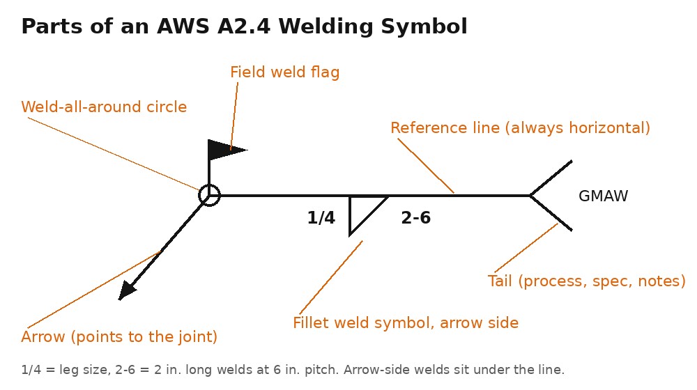
Every welding symbol is built on the same frame. Learn the frame first and the rest of the marks fall into place.
Reference Line
The reference line is the horizontal line at the center of the symbol. It is always required and always drawn level. Every weld symbol, size, and note attaches to it.
Arrow
The arrow runs from one end of the reference line to the joint on the drawing. The side of the joint it touches is the arrow side. The opposite side of that same joint is the other side.
Tail
The tail is the open V at the far end of the reference line. It holds supplementary information, such as the welding process, a specification, or a procedure number. Leave the tail off when there is nothing to add.
Basic Weld Symbol
The basic weld symbol sits on the reference line and shows the weld type: fillet, groove, plug, slot, and others. Its position on the line tells you which side of the joint to weld.
Dimensions and Supplementary Marks
Numbers to the left and right of the weld symbol give size, length, and spacing. Extra marks at the arrow junction, such as a flag or a circle, add instructions like field weld or weld all around.
Arrow Side vs Other Side
This rule trips up more beginners than any other mark. In AWS A2.4, a weld symbol under the reference line means weld the arrow side. A weld symbol over the reference line means weld the other side.
Miller Electric points out that this rule holds no matter which way the arrow faces. Symbols on both sides of the line mean weld both sides of the joint.
- Bevel and J-groove welds: only 1 piece gets prepared, so the arrow points at the piece that gets the bevel or J.
- Break in the arrow: a bent or broken arrow line marks the arrow-side member as the one to prepare.
- Plug and slot welds: arrow side or other side tells you which piece holds the hole or slot.
Common Basic Weld Symbols
The basic weld symbol is a picture of the weld’s cross section. These are the ones you will see most on fabrication drawings.
| Weld type | Symbol shape | Common joints | Reading tip |
|---|---|---|---|
| Fillet | Right triangle | Tee, lap, corner | The vertical leg is always drawn on the left |
| Square groove | 2 parallel lines | Butt | Any root opening is written on the symbol |
| V-groove | V shape | Butt | Both edges are beveled; groove angle and root opening are shown |
| Bevel groove | 1 vertical line and 1 slanted line | Butt, tee, corner | Arrow points to the beveled piece |
| U-groove | U shape | Butt | Both edges have a curved prep |
| J-groove | 1 vertical line and 1 J-shaped curve | Butt, tee, corner | Arrow points to the J-prepped piece |
| Flare-V groove | 2 outward curves | 2 curved parts | Groove depth goes to the left |
| Flare-bevel groove | 1 vertical line and 1 outward curve | Curved part to flat part | Groove depth and weld size go to the left |
| Plug or slot | Rectangle | Lap | Hole size left, pitch right |
Fillet welds are the most common symbol on structural and shop prints. Groove welds come next, mostly on butt joints in thicker plate.
Where the Numbers Go
Dimension placement follows fixed rules, so you can read a size without any notes on the print.
- Fillet size: left of the triangle. One number means equal legs. Two numbers mean unequal legs.
- Fillet length: right of the triangle. No length means weld the full joint between the given limits or until the joint changes direction.
- Intermittent welds: length and pitch, joined by a dash, go to the right. Length comes first. Pitch is measured center to center, so it is never the clear gap between welds.
- Groove depth: left of the groove symbol. The effective throat goes in parentheses after the depth.
- Groove angle and root opening: shown on the symbol for V and bevel grooves.
- Plug and slot welds: hole diameter or slot width on the left, pitch on the right. The number of plugs or slots goes in parentheses.
Worked Example: Intermittent Fillet Weld
Say the symbol shows a fillet triangle under the line, “1/4” on the left, and “2-6” on the right. That calls for a 1/4-inch fillet on the arrow side, laid as 2-inch welds at a 6-inch pitch.
Pitch runs center to center, so the clear space between beads is 6 minus 2, or 4 inches. If the same symbol also appears over the line, weld the other side too.
Supplementary Symbols
Supplementary symbols add instructions on top of the basic weld symbol. Most sit at the junction of the arrow and reference line or right next to the weld symbol.
| Mark | Looks like | Meaning |
|---|---|---|
| Weld all around | Open circle at the arrow junction | Weld the entire joint, such as a tube welded to a plate |
| Field weld | Flag at the arrow junction | Weld on site during installation; no flag means a shop weld |
| Melt-through | Mark opposite a groove symbol | Complete penetration with root reinforcement on the back side |
| Backing | Rectangle opposite the groove symbol | A backing strip is used; “R” inside means remove it after welding |
| Spacer | Rectangle that breaks the reference line | Spacer used in a double groove joint |
| Consumable insert | Mark opposite the groove symbol | An insert fuses into the weld; its class goes in the tail |
| Contour | Flat, convex, or concave line | Final weld face shape; flat on a groove weld is called flush |
Some older prints use a filled black circle for a field weld. Check the drawing date and legend if you see one.
Finishing Method Letters
A letter next to the contour mark tells you how to reach that finish. These letters come from the AWS finishing designations.
- C: chipping
- G: grinding
- H: hammering
- M: machining
- P: planishing
- R: rolling (a different R from the one inside a backing symbol)
- U: unspecified
What Goes in the Tail
The tail carries anything the frame can’t show. Common entries include the process (GMAW, SMAW, GTAW, FCAW), a welding procedure specification number, a filler metal class, the consumable insert class, or backing material and size.
No tail means no extra reference applies. If the tail is there, read it before you strike an arc.
AWS A2.4 vs ISO 2553 Symbols
Many drawings from outside North America follow ISO 2553 instead of AWS A2.4. The shapes look close, but a few rules change how you read them.
| Feature | AWS A2.4 | ISO 2553 |
|---|---|---|
| Other-side marker | Symbol over the reference line | A dashed identification line runs next to the solid reference line |
| Fillet size | Leg size, usually in inches | Throat thickness “a” or leg length “z”, in millimeters |
Check the title block for the standard before you weld. A 5 on an ISO print can mean a 5 mm throat, which gives a bigger weld than a 5 mm leg.
How to Read a Welding Symbol Step by Step
- Follow the arrow to the joint on the drawing.
- Find the weld symbol and note if it sits under the line (arrow side), over it (other side), or both.
- Read the size on the left and the length or length-pitch on the right.
- Check the arrow junction for a flag (field weld) or a circle (all around).
- Look for contour marks and finishing letters.
- Read the tail for the process, procedure, or filler metal.
Frequently Asked Questions
What Are the Three Main Parts of a Welding Symbol?
The three main parts are the reference line, the arrow, and the tail. The reference line is always horizontal and carries the weld symbol and sizes. The arrow points to the joint. The tail holds extra notes like the process or spec, and you can leave it off when nothing is needed.
What Does the Flag on a Welding Symbol Mean?
A flag where the arrow meets the reference line means a field weld. You make that weld on site during installation, outside the shop. A welding symbol with no flag is a shop weld. Some older drawings show a filled black circle for a field weld instead.
What Does a Circle on a Welding Symbol Mean?
An open circle where the arrow meets the reference line means weld all around. You run the weld around the entire joint, such as a square tube or round pipe welded to a base plate. The size and weld type on the reference line apply to the whole loop.
What Is the Difference Between a Weld Symbol and a Welding Symbol?
A weld symbol is the small shape that shows the weld type, like the triangle for a fillet weld or the V for a V-groove. A welding symbol is the full callout: reference line, arrow, tail, weld symbol, sizes, and any supplementary marks. AWS A2.4 uses both terms this way.
What Do the Numbers on a Weld Symbol Mean?
Numbers give the weld size and spacing. On a fillet weld, the number left of the triangle is the leg size and the number right of it is the length. Two numbers joined by a dash mean length and pitch, with pitch measured center to center between welds.
Final Words
Every welding symbol rests on 3 parts: the reference line, the arrow, and the tail. Read the side first, then the size and length, then the junction marks and the tail.
When a mark doesn’t match anything you know, go to the AWS A2.4 standard or the drawing legend. Ask the engineer before you guess, because a wrong side or size means cutting out the weld.