Disclosure: This post contains affiliate links and I will be compensated if you make a purchase after clicking through my links. Learn More
Calculating weld thickness is critical for safe and strong welded connections in construction, manufacturing, and repair work. Many people guess the weld size, but this often leads to weak joints or wasted material. A proper calculation uses engineering principles, not just experience or habit.
Understanding how to calculate weld thickness helps ensure structures can carry the intended load and meet safety codes.
This article explains clear steps for calculating weld thickness. It covers common weld types, important factors, industry standards, and useful examples. You will also learn about common mistakes, special cases, and tools that make the job easier. By the end, you will know how to get accurate weld sizes for most situations.
Why Weld Thickness Matters
Weld thickness is not just a number on a drawing. It decides if a weld can carry the expected forces. If the weld is too thin, the joint may fail under stress. If the weld is too thick, it wastes material, increases cost, and can even weaken the base metal due to excess heat.
Most engineering codes set minimum weld sizes for safety. For example, AWS D1.1 and ISO 2553 provide guidance for common structures. Welding inspectors check thickness during quality control. Poor calculation can lead to failed inspections, rework, or even dangerous accidents.
Key Types Of Welds
Before learning how to calculate weld thickness, you need to know the main weld types. Each type has its own way to measure and specify thickness.
Fillet Weld
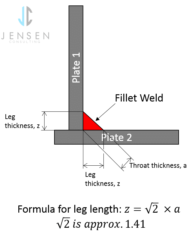
A fillet weld joins two surfaces at a right angle. It forms a triangle shape in the cross-section. You measure its thickness as the “leg length” or the size of the triangle.
Groove Weld
A groove weld joins two pieces edge-to-edge. The weld fills a groove between the parts. The thickness is the depth of the groove filled with weld metal.
Plug And Slot Welds
Plug welds and slot welds fill holes or slots in one piece to join it to another. Weld thickness is the depth of the hole or slot.
Flare Bevel And Flare V Welds
These welds join round bars or pipes to flat plates. Thickness depends on the groove created by the round shape.
Understanding these types is important because calculation methods differ for each.
Basic Principles Of Weld Thickness Calculation
Weld thickness depends on several factors:
- Load Type: Is the weld in tension, shear, or both?
- Base Metal Thickness: The weld should not be thicker than the thinner part.
- Weld Type: Fillet, groove, plug, or slot.
- Code Requirements: Most jobs follow standards like AWS, ISO, or EN codes.
- Service Conditions: Will the weld see vibration, corrosion, or fatigue?
Calculating weld thickness uses formulas. These formulas balance strength, safety, and material cost.
How To Calculate Fillet Weld Thickness
Fillet welds are the most common. They appear in beams, brackets, frames, and pipes. Calculating their size is straightforward if you know the basics.
Understanding The Fillet Weld
A fillet weld looks like a right triangle in cross-section. The two short sides are the legs. The longest side is the throat.
Formula For Fillet Weld Size
The main measure is the leg length (denoted as ‘a’). The strength of a fillet weld is mostly based on the throat, which is the shortest distance from the root to the hypotenuse.
Effective throat (te) = a × 0.707
This factor comes from the geometry of a right triangle.
Calculating Required Leg Length
Suppose you need a weld to resist a certain force. Use this basic process:
- Find the total required weld area.
- Use the throat length to find the leg length.
- Check that the leg length does not exceed the thinnest plate.
Step 1: Find Required Weld Area
If you know the force (F) and the allowable stress for the weld metal (S), the required area (A) is:
A = F / S
Step 2: Relate Area To Weld Length And Throat
The area of a fillet weld = Effective throat × Length of weld
So:
A = Te × L
Step 3: Substitute For Effective Throat
Remember, Te = A × 0.707
So:
A = A × 0.707 × L
Step 4: Solve For Leg Length
A = A / (0.707 × L)
If you know A and L, you can find the weld size (a).
Example Calculation
Suppose you need to join two plates with a fillet weld to carry a 20,000 N force. The allowable weld stress is 140 MPa (N/mm²). The weld is 100 mm long.
- Find required area:
A = 20,000 N / 140 N/mm² = 143 Mm²
- A = A / (0.707 × L) = 143 / (0.707 × 100) = 143 / 70.7 ≈ 2.02 mm
You would round up and choose a 3 mm leg length for safety and code compliance.
Important Notes
- Most codes set minimum fillet weld sizes, often 3 mm to 6 mm for common structures.
- Welds should not be thicker than the base metal.
- If there are multiple welds, split the load between them.
Groove Weld Thickness Calculation
Groove welds fill a groove between two pieces. The groove can be square, V, U, J, or bevel-shaped.
Groove Weld Types
- Complete joint penetration (CJP): The weld metal fills the entire groove, and the joint is as strong as the base metal.
- Partial joint penetration (PJP): Only part of the groove is filled.
Calculating Groove Weld Size
For a CJP weld, the thickness is usually the same as the thinnest base metal. For a PJP weld, you calculate the required weld size based on the applied load.
Step 1: Find Required Throat Depth
The formula is similar to fillet welds, but the throat is the depth of weld metal in the groove.
A = F / S
A = Effective Throat × Weld Length
So:
Effective Throat = A / Weld Length
Example Calculation
Suppose two 8 mm plates are butted together and must carry a 24,000 N load. Allowable weld stress is 160 MPa, weld length is 120 mm.
- Required area:
A = 24,000 / 160 = 150 Mm²
- Effective throat = A / L = 150 / 120 = 1.25 mm
But usually, codes will require a minimum throat, and for CJP, you must weld the full thickness (8 mm in this case).
Special Considerations
- For thick plates, preheat may be needed to avoid cracks.
- The groove angle and root opening affect the amount of weld metal required.
Plug And Slot Welds
Plug and slot welds are less common but appear in automotive and sheet metal work. The thickness is the depth of the hole filled with weld metal.
Steps For Calculation
- Decide the load the weld must carry.
- Find the allowable stress.
- Area = π × (hole radius)² for a plug weld.
- Weld thickness = area / perimeter of the hole (for strength in shear).
Most codes have minimum thickness and diameter rules.
Weld Thickness Calculation: Codes And Standards
Every project should follow a recognized code. These codes set minimum and maximum weld sizes, inspection rules, and safety factors. The most widely used are:
- AWS D1.1 (Structural Welding Code – Steel)
- ISO 2553 (Welding and Allied Processes)
- EN 1993 (Eurocode for Steel Structures)
These codes give tables for minimum weld sizes based on plate thickness. Here is an example summary based on AWS D1.1:
| Base Metal Thickness (mm) | Minimum Fillet Weld Size (mm) | Maximum Fillet Weld Size (mm) |
|---|---|---|
| Up to 3 | 2 | Not specified |
| 3 to 6 | 3 | Not specified |
| 6 to 13 | 5 | Not more than thickness of thinner part – 1.5 mm |
| Over 13 | 6 | Not more than thickness of thinner part – 3 mm |
Always check the latest code for your project.
Factors That Influence Weld Thickness
Several details affect the correct weld size. Missing any can cause problems.
1. Base Metal Thickness
Never make the weld thicker than the thinnest base metal. It does not improve strength and can cause more distortion.
2. Joint Type And Position
Welds in overhead or vertical positions may need to be smaller to prevent sagging.
3. Type Of Load
Dynamic or impact loads need stronger, often larger welds. Fatigue loads also need special care.
4. Access For Welding
Limited access may force you to use smaller welds or special processes.
5. Welding Process
Manual welding, MIG, TIG, and automated processes all have different limits for reliable weld thickness.
6. Heat Input
Too much weld metal can overheat the base metal, causing distortion or cracking.
7. Corrosion And Service Life
In aggressive environments, thicker welds may help resist corrosion, but proper surface treatment is usually better.

Credit: www.weldingandndt.com
Tools For Measuring And Calculating Weld Thickness
Accurate weld thickness starts with good measuring tools and calculation methods. Some common tools include:
- Weld fillet gauges: Simple, handheld tools to check leg length.
- Calipers: For precise measurement of weld bead.
- Weld size charts: Quick reference for standard weld sizes.
- Engineering calculators or apps: Many welding codes offer online tools.
- CAD software: Can check weld sizes on drawings.
Here is a quick comparison of common tools:
| Tool | Accuracy | Ease of Use | Best For |
|---|---|---|---|
| Fillet Gauge | ±0.5 mm | High | Shop floor |
| Caliper | ±0.1 mm | Medium | Inspection |
| Weld Size Chart | Varies | Very High | Design stage |
| Calculator/App | High | High | Engineering office |
Step-by-step Guide For Calculating Weld Thickness
A simple process helps avoid mistakes. Follow these steps for most common welds:
- Identify the weld type. Is it fillet, groove, plug, or slot?
- Check the base metal thickness. Use the thinner part for sizing.
- Find the applied load and direction. Know if it’s shear, tension, or both.
- Get the allowable weld stress. Use material data or code values.
- Calculate the required weld area. Use A = F / S.
- Select weld length. Use drawing or code minimums.
- Calculate weld size. For fillet welds, a = A / (0.707 × L).
- Check code minimums and maximums. Adjust as needed.
- Specify the weld on the drawing. Use standard symbols.
- Verify with a weld gauge after welding. Inspect for quality.
Common Mistakes In Weld Thickness Calculation
Many beginners, and even experienced welders, make errors. Avoid these pitfalls:
- Guessing weld size without calculation or code check.
- Ignoring load direction. Shear and tension require different checks.
- Not checking code minimums. Leads to failed inspections.
- Oversizing the weld. Wastes time and material, can cause distortion.
- Using wrong allowable stress. Always check the material and process.
- Not considering joint access. May specify a weld that cannot be made.
- Skipping inspection. Always measure the actual weld.
Advanced Considerations
Some projects need more complex calculations. These include:
Fatigue And Cyclic Loads
Welds in bridges, cranes, or moving equipment face repeated loading. Fatigue cracks can start even in thick welds if design is poor. Codes like AWS D1.1 have special rules for fatigue.
Combined Loads
If a weld faces shear and tension together, combine the stresses. This often means a larger weld.
Multiple Welds
Distribute the load among all welds. If one weld fails, the others may get overloaded.
Heat-affected Zone (haz)
Welding changes the base metal near the joint. The HAZ can be weaker than the weld or the rest of the metal. Control heat input and use proper welding technique.
Backing Bars And Back Welds
Sometimes, a backing bar or a back weld is used to ensure full penetration. Factor these into the calculation.
Non-destructive Testing (ndt)
For critical structures, X-ray, ultrasound, or magnetic particle testing checks weld quality. Bad welds must be repaired, not just made bigger.
Examples Of Weld Thickness Calculation
Let’s work through a few practical examples.
Example 1: Fillet Weld In Shear
A bracket must support a 10,000 N load. The weld length is 80 mm, allowable stress is 150 MPa.
Required Area: 10,000 / 150 = 66.67 Mm²
Weld size: a = 66.67 / (0.707 × 80) = 66.67 / 56.56 ≈ 1.18 mm
Choose a 3 mm weld (minimum by code).
Example 2: Groove Weld For Plate Butt Joint
Join two 12 mm plates for a load of 30,000 N. Allowable stress is 180 MPa. Weld length is 120 mm.
Area: 30,000 / 180 = 166.7 Mm²
Throat Required: 166.7 / 120 = 1.39 Mm
But for a CJP weld, you use the full thickness, so weld size is 12 mm (plate thickness).
Example 3: Plug Weld
A car body uses plug welds to join thin sheets. Each plug is 8 mm in diameter (radius 4 mm). Allowable stress is 100 MPa. Each plug must carry 2,500 N.
Area Per Plug: Π × 4² = 50.27 Mm²
Required Area: 2,500 / 100 = 25 Mm²
So, one plug is enough. Weld thickness equals sheet thickness (say, 1. 5 mm).
Special Cases
Sometimes, you must adjust calculations for special shapes or conditions.
- Curved joints: Use the developed length (curve length) for weld area.
- Intermittent welds: Only part of the joint is welded. Use total welded length in calculations.
- Dissimilar metals: Use the lower allowable stress.
- High-temperature service: Reduce allowable stress per code.
Credit: restoric.co.uk
Specifying Welds On Drawings
Engineers use standard symbols to show weld size on drawings. For fillet welds, the leg length is shown (e. g. , 6 mm). For groove welds, the depth or penetration is shown.
A typical drawing might show:
- 6 mm fillet weld, both sides
- 10 mm groove weld, full penetration
Use ISO or AWS symbols for clarity.
Weld Thickness And Quality Control
After welding, inspectors check weld thickness to confirm it matches the design. This is done by:
- Visual inspection
- Weld gauge measurement
- NDT for critical joints
If the weld is too small, it must be repaired. If too large, it may be accepted, but check for distortion or cracks.
Real-world Data: Weld Failures
Data from engineering failures show that poor weld sizing is a common cause of structural accidents. In a 2015 survey, 24% of steel structure failures involved welds that were too small or not made as shown on drawings. Proper calculation and inspection greatly reduce this risk.
Digital Tools And Resources
Many engineers use software to check weld sizes. Programs like Tekla, AutoCAD, and online calculators from the American Welding Society help speed up the process.
For detailed code rules, see the Wikipedia welding symbol guide.
Frequently Asked Questions
How Do I Choose Between Fillet And Groove Welds?
The choice depends on joint type, required strength, and access. Fillet welds are faster and good for right-angle joints. Groove welds allow full penetration and are better for high-strength joints.
Can I Use A Weld Thicker Than The Base Metal?
No, the weld should not be thicker than the thinner base metal. Extra weld metal does not increase strength and may cause problems.
What Happens If The Weld Is Too Small?
A small weld may fail under load. It can also lead to failed inspections, fines, or safety risks. Always check code minimums.
How Do I Measure Weld Thickness After Welding?
Use a weld fillet gauge for fillet welds or a caliper for groove welds. Visual checks are not enough for important work.
Do I Need To Recalculate Weld Size If Using A Different Welding Process?
Yes. Different processes have different penetration and strength. Always check the allowable stress and adjust calculation if you change the process.
Final Thoughts
Calculating weld thickness is not guesswork. It needs a clear understanding of joint type, loading, and code requirements. A careful calculation saves time, money, and prevents failures. Always use the correct formulas, check the codes, and inspect the finished weld.
With the right approach, your welds will be safe, strong, and reliable.

Credit: www.youtube.com