Disclosure: This post contains affiliate links and I will be compensated if you make a purchase after clicking through my links. Learn More
Metal Inert Gas (MIG) welding is popular because it is fast, precise, and works on many metals. But to get strong, clean welds, you need more than just a good welder and wire. The gas flow rate you use makes a big difference. Too little gas can cause defects. Too much wastes money and can even weaken your welds. Many welders struggle with finding the right flow rate, and charts can help—but only if you understand how to use them. This article explains MIG welding gas flow rates in detail, with charts, examples, and expert advice.
Why Mig Welding Needs Shielding Gas
MIG welding uses a wire electrode and a shielding gas. The wire feeds through a gun, melts, and joins the metal pieces. The shielding gas protects the weld pool from air. Without it, oxygen and nitrogen in the air cause porosity, spatter, and weak welds. The most common shielding gases for MIG welding are:
- 100% CO2 (Carbon Dioxide)
- 75% Argon / 25% CO2 (C25)
- 100% Argon (mainly for aluminum)
Using the right gas mix is important, but so is using the right amount per minute—this is the gas flow rate.
Shielding gas also affects the arc’s stability and the way the molten metal flows into the joint. For example, argon makes the arc smoother, while CO2 can make it more forceful and create more spatter. If the shielding gas is interrupted for even a second, the weld can become contaminated, leading to costly repairs or weak joints.
This is especially true when welding metals that oxidize easily, such as aluminum or stainless steel. For these metals, even a tiny amount of air can cause color changes, cracks, or brittle welds. That’s why understanding the role of shielding gas and flow rate is critical for every welder, whether you are working on cars, structures, or fine art.
What Is Gas Flow Rate In Mig Welding?
Gas flow rate means how much shielding gas leaves the nozzle each minute. It is measured in cubic feet per hour (CFH) or liters per minute (LPM). Most MIG welders adjust this with a regulator or flowmeter. The right flow rate depends on:
- Type of gas
- Nozzle size
- Metal thickness
- Welding position
- Wind or drafts
A typical range is 15–35 CFH (7–16 LPM). Too low, and air gets in. Too high, and you waste gas and may suck in air due to turbulence.
The flow rate is not the same as pressure. Some beginners confuse tank pressure with flow rate, but they are different. Pressure tells you how much gas is left in the cylinder; flow rate tells you how fast the gas is coming out to protect your weld.
Always use the flowmeter reading near the torch, not just the tank gauge. If your flow is set too low, you might not notice a problem until the weld fails a test or inspection. On the other hand, high flow can seem safe, but it often causes hidden defects due to turbulence pulling in outside air.
This is why careful adjustment and checking are so important.

Credit: www.arccaptain.com
Mig Welding Gas Flow Rate Chart
A gas flow rate chart helps you set the correct amount for your job. Here is a common chart for MIG welding on steel and aluminum:
| Material | Gas Type | Nozzle Size (in) | Flow Rate (CFH) | Flow Rate (LPM) |
|---|---|---|---|---|
| Steel | 75% Argon / 25% CO2 (C25) | 1/2″ – 5/8″ | 20–30 | 10–14 |
| Steel | 100% CO2 | 1/2″ – 5/8″ | 20–35 | 10–16 |
| Aluminum | 100% Argon | 1/2″ – 5/8″ | 18–30 | 8–14 |
| Stainless Steel | 98% Argon / 2% CO2 | 1/2″ – 5/8″ | 20–30 | 10–14 |
These values work for most MIG jobs indoors, with no wind. But they are not “one size fits all. ”
It’s also important to remember that some jobs use gas lenses or special nozzles, which can change the ideal flow rate. Always check your equipment’s manual or ask a supplier if you’re not sure. For beginners, sticking to the middle of the recommended range often gives the best results, but always adjust based on your test welds.
Key Factors That Affect Gas Flow Rate
Different jobs need different flow rates. Here’s what you must consider.
1. Nozzle Size
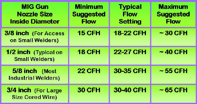
A bigger nozzle covers a wider area and needs more gas to protect the weld. If you use a small nozzle, reduce the flow rate. If you use a large nozzle, increase it slightly.
For example, if you switch from a 1/2″ to a 3/4″ nozzle, you may need to add 2–5 CFH to get full coverage. Some welders use tapered nozzles for tight spaces or corners; these can often work with less gas.
Always check for even gas coverage by making a few test welds and inspecting the bead and surrounding area.
2. Welding Environment
Welding outdoors or in a drafty shop means gas can blow away. You might need to raise the flow rate to 35–40 CFH, but be careful not to go too high. Indoors, you can use lower settings.
In some cases, using curtains or portable windbreaks can help you maintain a steady shield and reduce the need for extra gas. If you’re welding in a confined space, ventilation is also important for safety, but strong airflow near the weld should be avoided.
3. Metal Type
Some metals, like aluminum, need higher purity gas and a steady shield. Stainless steel needs careful control, too. Adjust flow rate for each metal as the chart suggests.
Aluminum is especially sensitive to contamination, so even small mistakes with gas flow can lead to bad welds. Stainless steel can develop a sugared or rough surface if the shielding is poor. Always double-check your setup if you switch materials during a project.
4. Welding Position
Welding overhead or vertical can make gas shielding less effective. Slightly increase flow rate in these positions to keep the weld pool protected.
Gravity can cause the molten metal to flow away from the shield, especially if you are working on a large piece. For critical joints, consider practicing on scrap in the same position to fine-tune your settings.
5. Wire Feed Speed And Amperage
High wire feed speed or high current melts more metal, which can blow away gas or make the arc unstable. Sometimes, you need a higher flow rate.
As a rule of thumb, faster welding requires a bit more gas to keep up with the increased metal transfer. However, if you notice excessive spatter or a ragged bead, check if your flow is too high as well.
6. Gas Type
Argon is heavier than air and stays around the weld better than CO2. With pure argon, you can often use a slightly lower flow rate than with CO2 or mixes.
If you use a blend, check the manufacturer’s recommendations, as some mixes are optimized for specific wire types or welding speeds. Switching gases without adjusting the flow can lead to unexpected results.
Credit: www.netwelding.com
How To Set Gas Flow Rate Correctly
Many beginners set the regulator by “feel” or just copy another welder. This is risky. Here’s a step-by-step guide:
- Check the chart for your metal, gas, and nozzle size.
- Set the regulator to the recommended CFH or LPM.
- Listen and watch: Too little gas makes the arc pop and welds look porous. Too much gas makes a loud hissing noise and can cause turbulence.
- Test on scrap metal. Look for smooth welds with no holes or spatter.
- Adjust for wind if you work outdoors.
Pro tip: Never turn the gas all the way up “just to be safe.” This wastes gas and can make the shield worse.
Some welders also check the gas flow at the nozzle using a simple flow tester or bubble gauge. These small tools fit over the end of the nozzle and help verify the real flow rate. This is especially useful if your equipment is older or if you suspect your regulator is not accurate.
Checking your flow at the nozzle, rather than just at the tank, can help catch leaks or blockages that might go unnoticed otherwise.
Common Problems From Wrong Gas Flow Rate
Many welders see poor welds and blame the wire, the machine, or their technique. Often, the real problem is gas flow.
- Low flow causes porosity (small holes in the weld), weak welds, and spatter.
- High flow creates turbulence, which can suck in air and cause defects. It also wastes gas.
If you see these problems, check your flow rate before you change other settings.
Porosity can sometimes be hidden inside the weld and only appears when you cut or grind the joint. Turbulence from high flow can also cause the weld bead to become irregular or trap tiny bubbles, making the weld weaker. Other signs of bad flow include a change in the arc sound (it should be smooth, not sharp or hissing), and black soot or discoloration around the weld.
If you encounter these issues often, it’s a good idea to keep a log of your typical settings so you can troubleshoot faster in the future.

Credit: www.scribd.com
Examples Of Gas Flow Rate Settings
Let’s look at some sample setups for common jobs.
Example 1: Welding Mild Steel With C25 Gas
You want to weld mild steel with a 0. 030″ wire, using a 1/2″ nozzle, indoors. The chart suggests 20–30 CFH. Start at 25 CFH. Check your welds. If you see porosity, try 28 CFH. If it’s loud and hissing, lower to 22 CFH.
If you switch to a smaller wire or thinner sheet metal, you might get good results at the lower end—around 20 CFH. Always do a few test beads and brea