Disclosure: This post contains affiliate links and I will be compensated if you make a purchase after clicking through my links. Learn More
Welding is a skill that depends on details. One of the most important details is the correct welding electrode amp chart. The right amperage ensures strong welds, prevents problems, and helps the welding process stay safe and steady. Many beginners struggle with amperage. Even experienced welders check amp charts for new jobs or unfamiliar electrodes. This article gives a full guide to understanding and using a welding electrode amp chart. If you want reliable welds, you need this knowledge.
Understanding amperage is not just about numbers. It affects the weld’s quality, the work speed, and the safety of the operator. Using the wrong amperage can cause many problems—some minor, some serious. This article explains everything about amp charts, including how to read them, why they matter, and how to use them in real jobs.
You will see practical examples, common mistakes, and expert tips. By the end, you will know how to pick the right settings for any welding project.
What Is A Welding Electrode Amp Chart?
A welding electrode amp chart shows the recommended amperage (electric current) for different welding electrodes and their sizes. Each type of electrode works best within a certain amp range. If you use too little current, the electrode may stick or not melt well. If you use too much, you can burn through the metal or make a weak weld.
Most amp charts are simple tables or lists. They show the electrode type, diameter, and recommended amperage. Some charts add more details, such as the type of welding position (flat, vertical, overhead), type of current (AC or DC), and base metal thickness.
Amp charts are important for all common welding types, including:
- Shielded Metal Arc Welding (SMAW), also called stick welding
- Gas Metal Arc Welding (GMAW/MIG)
- Flux-Cored Arc Welding (FCAW)
- Tungsten Inert Gas Welding (GTAW/TIG)
Each process needs its own chart because electrodes and wires differ. For example, a MIG welding wire requires much different amperage compared to a stick electrode of similar diameter. That’s why using the right chart for the right process is critical for good results.
Some charts are also color-coded or include extra notes, especially those found in welding textbooks or on the back of electrode boxes. These small details can make it easier to find the right settings quickly, even for those who are just starting.
Why Amperage Matters In Welding
Amperage controls how much heat goes into the weld. The right amp setting melts the electrode at the correct rate and gives a stable arc. If you guess or use random numbers, you risk these problems:
- Cold Welds: Low amperage gives shallow welds that are weak and may crack.
- Burn-Through: High amperage melts the base metal too much, creating holes or thinning the metal.
- Spatter and Rough Beads: Wrong settings cause messy welds and more cleanup.
- Electrode Problems: Too little current makes the electrode stick, while too much burns it fast.
Amp charts help avoid these mistakes. They give you a starting point, so you waste less time and materials.
If you are welding something important—like a part that holds weight or is exposed to vibration—weld quality is not just about looks. It’s about safety and strength. A weld that looks good but has a cold joint can fail without warning.
Amperage is a key factor in getting the needed fusion between the base metals.
Another detail: correct amperage makes welding less tiring. With the right setting, you can move the electrode smoothly, avoid fighting a sticking rod, and get a more predictable arc. This reduces stress and helps you focus on technique instead of fixing problems caused by bad settings.
How To Read A Welding Electrode Amp Chart
Amp charts look simple, but you need to read them carefully. Here’s a common layout:
| Electrode Type | Diameter (mm) | Diameter (inch) | Amperage Range (A) | Current Type | Welding Position |
|---|---|---|---|---|---|
| E6013 | 2.5 | 3/32 | 70–100 | AC/DC | All |
| E7018 | 3.2 | 1/8 | 90–150 | AC/DC | Flat, Horizontal |
| E6011 | 4.0 | 5/32 | 110–160 | AC/DC | All |
Key parts to check:
- Electrode type: Each electrode has a unique code (like E6013).
- Diameter: Measured in millimeters and inches.
- Amperage range: Suggested current in amps.
- Current type: Some electrodes only work with AC or DC.
- Position: Some electrodes weld better in certain positions.
You pick the right row based on the electrode you use. Then you choose an amp value within the recommended range.
Some amp charts also have footnotes. For example, they might mention “reduce amps by 10% for overhead welding” or “increase amps for long cable runs. ” These notes can make a big difference, especially for jobs outside the normal range.
Don’t skip them.
If you are unsure about the electrode code, look for the information printed on the rod itself or on the package. Manufacturers usually follow standard coding, but sometimes there are local variations. When in doubt, always check the packaging or ask an experienced welder before setting your machine.
Common Welding Electrodes And Their Amp Ranges
Different jobs need different electrodes. Here are some common electrodes and their typical amp ranges:
| Electrode | Diameter (mm) | Diameter (inch) | Amperage Range (A) | Usual Application |
|---|---|---|---|---|
| E6010 | 2.5 | 3/32 | 40–85 | Pipe welding, root passes |
| E6011 | 3.2 | 1/8 | 75–125 | General purpose, repair |
| E6013 | 2.5 | 3/32 | 50–90 | Sheet metal, thin plate |
| E7018 | 4.0 | 5/32 | 130–180 | Structural, heavy plate |
Two insights most beginners miss:
- Electrode brand can change amp range. Not all E7018 electrodes behave the same. Always check the package.
- Base metal thickness matters. Even if the chart gives a wide range, thicker metal usually needs the higher side of the range.
For example, some E7018 rods from premium brands can be used at slightly lower amps without sticking, while cheaper rods may need more heat to start and keep a stable arc. If you switch brands, always do a test run before starting the main weld.
Another example: if you weld on rusty steel, you may need to increase amps by 5–10 to help penetrate the rust layer, but this can also increase spatter. Cleaning the surface first is a better solution, but sometimes, in field repairs, you have no choice but to adjust the amps.
How To Pick The Right Amperage
Choosing the right amperage is not just about the chart. Real welding conditions may need you to adjust the number. Follow these steps for good results:
- Start with the chart recommendation. Set your machine to the middle of the range.
- Check the electrode package. Sometimes, the amp range is printed on the box. Use that as your reference.
- Consider the metal thickness. If the metal is thin, stay at the low end of the range. For thick steel, move to the high end.
- Test on scrap metal. Before welding your project, run a short bead on similar scrap. Adjust up or down if needed.
- Watch the weld pool. If the bead is too narrow or the arc is unstable, increase amps slightly. If the pool is too wide or the metal burns, reduce amps.
- Listen to the arc. A smooth, steady sound means good settings. Popping or sputtering means you need adjustment.
Practical example:
If you weld 6mm steel plate with a 3. 2mm E7018 rod, the chart says 90–150 amps. Start at 120 amps. If the arc feels weak, go up to 130. If you see burn-through, drop to 110.
A small detail: humidity in the air can affect how rods behave. On damp days, some electrodes (especially low-hydrogen types like E7018) can absorb moisture, making them harder to start. In this case, try to keep your rods in a dry box, and don’t be surprised if you need to increase amps slightly.
For thin metals, it’s better to do several short welds rather than one long bead. This helps prevent overheating and warping. Always start at the low end of the amp range, and move quickly.
Factors That Affect Amperage Choice
Many things influence your amperage setting. Here are some key factors:
1. Electrode Size
Larger electrodes need more current to melt. If you use a small rod with high amps, it will burn too fast. If you use a big rod with low amps, it will stick or not melt well.
2. Welding Position
Flat position needs more heat than vertical or overhead. If you weld overhead, too much current makes the weld drip or sag. Lower your amps by 10–15% for vertical or overhead welding.
3. Base Metal Thickness
Thicker metal needs more amps for deep fusion. If you use high amps on thin metal, you risk burn-through.
4. Type Of Joint
Butt joints and fillet joints may need different amps. Fillet welds often use a bit less current.
5. Welding Machine Type
Old machines may not give the exact amps you set. Digital machines are more precise. Always test before starting your main project.
A tip most miss:
Cable length affects amps. Long or thin cables can cause voltage drop. If you use extension cables, you may need to increase your amps slightly.
Another example: if you weld outdoors in windy conditions, the arc can become unstable. Sometimes, welders increase amps to try to keep the arc steady, but this can make the weld messy. In these cases, use windshields or move to a more sheltered spot if possible, rather than just adjusting amperage.
Amperage Chart For Popular Stick Electrodes (smaw)
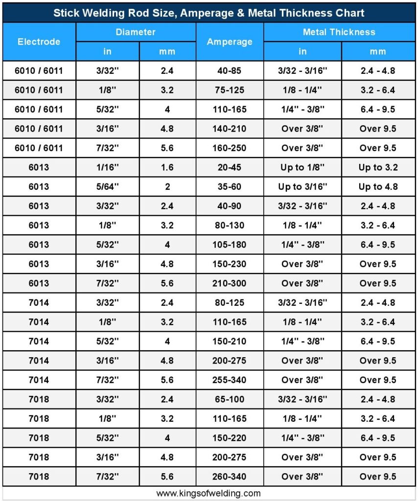
Here’s a helpful amp chart for common stick welding electrodes and sizes:
| Electrode | Diameter (mm) | Diameter (inch) | Amperage Range (A) |
|---|---|---|---|
| E6010 | 2.5 | 3/32 | 40–85 |
| E6010 | 3.2 | 1/8 | 75–125 |
| E6011 | 2.5 | 3/32 | 50–90 |
| E6011 | 4.0 | 5/32 | 110–160 |
| E6013 | 2.0 | 5/64 | 40–70 |
| E7018 | 2.5 | 3/32 | 70–110 |
| E7018 | 4.0 | 5/32 | 130–180 |
Always check your machine manual and electrode box for the best numbers.
You might notice that some electrodes have a wide amp range. For example, an E6010 3. 2mm rod can run anywhere from 75 to 125 amps. The exact setting depends on your project, but always stay within the range. If you go higher, you risk damaging the flux coating, which can lead to porosity in the weld.
Amperage Chart For Mig Welding (gmaw)
MIG welding uses wire instead of rods. The amp chart for MIG uses wire diameter and metal thickness:
| Wire Diameter (mm) | Wire Diameter (inch) | Amperage Range (A) | Metal Thickness (mm) |
|---|---|---|---|
| 0.6 | 0.023 | 40–90 | 0.8–3.0 |
| 0.8 | 0.030 | 50–130 | 1.0–4.0 |
| 1.0 | 0.040 | 70–180 | 2.0–8.0 |
| 1.2 | 0.045 | 100–250 | 4.0–12.0 |
Expert tip:
Wire feed speed and voltage also affect MIG welding. Start with the chart for amps, but be ready to adjust wire speed for a smooth arc.
If your wire burns back to the contact tip, your amps or wire speed may be too low. If you get lots of spatter, the amps could be too high or the voltage too low. Listen for a smooth “hissing” sound; a harsh, popping arc means settings need adjustment.
A MIG chart is only a starting point. If you change from CO2 shielding gas to argon/CO2 mix, you may need to lower your amps slightly for the same thickness and wire size.

Credit: bakersgas.com
Tig Welding Amperage Chart
TIG welding needs more control. The amperage depends on the tungsten size and the metal type. Here’s a basic chart:
| Tungsten Diameter (mm) | Tungsten Diameter (inch) | Amperage Range (A) | Metal Type |
|---|---|---|---|
| 1.0 | 0.040 | 15–80 | Aluminum, Steel |
| 1.6 | 1/16 | 70–150 | Aluminum, Steel |
| 2.4 | 3/32 | 150–250 | Steel, Stainless |
Non-obvious insight:
Always start with the lower end of the range for thin materials or when welding out of position.
TIG welding also allows you to control the amperage with a foot pedal or finger control. If you find the weld pool getting too large, you can “back off” the amps in real-time. This is especially useful for thin aluminum or stainless steel.
Another detail: Different tungsten types (pure, thoriated, ceriated) handle amps differently. Check your electrode’s markings and manufacturer recommendations.
Flux-cored Welding Amperage Chart (fcaw)
Flux-cored welding uses a tubular wire. The amp chart is similar to MIG, but the wires are different:
| Wire Diameter (mm) | Wire Diameter (inch) | Amperage Range (A) | Metal Thickness (mm) |
|---|---|---|---|
| 0.8 | 0.030 | 50–140 | 1.0–5.0 |
| 1.2 | 0.045 | 120–250 | 3.0–12.0 |
Use the chart as a starting point and adjust as needed for your job.
For FCAW, the correct amperage also depends on whether you are using self-shielded or gas-shielded wire. Self-shielded wires often need slightly higher amps for the same thickness, and too little heat can cause slag inclusions.
If you weld thick structural steel with FCAW, check if your wire manufacturer recommends a specific range for vertical-up or overhead welding. Sometimes they give two sets of numbers.

Credit: www.scribd.com
How To Adjust Amperage For Special Situations
Sometimes, you need to change the chart settings for special cases:
- Thin metal (Use the lowest amp in the range. Move fast to prevent holes.
- Out of position welds: Lower the amps 10–15% to keep the weld pool small.
- Dirty or rusty metal: Slightly higher amps can help burn through contamination, but clean metal is always better.
- Long cable runs: Increase amps by 5–10% if your welding cables are very long.
Advanced tip:
For very important welds, do a bend or break test on scrap metal. This checks if your settings give strong welds.
Another example: If you are working in a cold workshop or outdoors in winter, the metal cools faster, so you may need to increase amps by 5–10%. If you weld outside in hot weather, you might need less. Always adjust based on feel and test welds.
If you need to weld galvanized steel, use the lower end of the amp range and grind off as much coating as possible. Galvanized fumes are toxic, so always work with good ventilation and a respirator.
Common Mistakes With Amp Charts
Many welders make the same errors when using amp charts. Here are the most common:
- Ignoring the chart completely. Guessing leads to bad welds.
- Always using the highest amp in the range. This often causes burn-through.
- Not adjusting for position. Welding vertical or overhead with flat-position amps leads to drips and sagging.
- Forgetting to check the electrode package. Some rods have special coatings that change the best amp.
- Using old or damp electrodes. These may need more current but still make weak welds.
Avoid these mistakes for better results and less wasted material.
Another common mistake: switching between metric and imperial units without noticing. Always double-check rod size and chart units. A 1/8″ rod is not the same as a 3mm rod, and using the wrong setting can cause problems.
Credit: www.kingsofwelding.com
How To Make Your Own Amp Chart
If you weld often, you may want to make a custom amp chart. Here’s how:
- Track your best settings. For each electrode, write down the amps that work best for your jobs.
- Note the machine type. Settings can change between machines.
- List metal thickness and position. These details help you remember why you chose a setting.
- Keep it simple. Use a notebook or a phone app for easy access.
A personal chart saves time and reduces errors.
Some welders also write notes on their machines with a marker or use stickers for quick reference. Others keep a laminated chart in their toolbox, especially if they do mobile repair work. Over time, these personal notes become more valuable than any printed chart, because they are based on your own experience.
Safety Tips When Setting Amperage
Welding with the wrong amperage is not just a quality problem. It can also be dangerous. High amps can lead to:
- Excessive spatter that burns skin or starts fires
- Arc blow, which can damage equipment
- Overheating cables or machines
Always use gloves, a proper helmet, and check your cables for heat. Never exceed the maximum amp rating for your electrode or machine.
If you notice your leads or machine getting hot during use, stop and let things cool down. Overheating can melt insulation and create an electric shock risk. Always follow the duty cycle listed in your machine manual—if it says 60% at 120 amps, do not run the machine more than 6 minutes out of 10 at that setting.
How Amp Charts Help In Welding Certification Tests
Welding tests for certifications (like AWS or ASME) have strict requirements. Test pieces must have full penetration, good appearance, and no defects. Amp charts help you pick the right starting point so you don’t fail for simple mistakes.
Extra tip:
Practice with the exact electrode and settings you will use in the test. Small changes in amps can be the difference between passing and failing.
Test supervisors often check your settings before the test begins. If you don’t know your amp setting or are guessing, they may not let you start. Use the amp chart to show you are prepared, and always do a practice weld on a scrap piece first.
Where To Find Reliable Amp Charts
You can find amp charts in these places:
- Electrode packaging: Most trusted source for that specific rod.
- Welding machine manuals: Good for general guidance.
- Reputable websites: Like Lincoln Electric.
- Welding textbooks: Detailed but sometimes too technical for beginners.
Avoid random internet charts unless they come from known brands.
If you buy electrodes from a welding supply store, ask for the manufacturer’s chart. Some brands offer wallet-sized cards or posters with amp recommendations. These are handy for keeping in your workshop.
Two Insights Most Beginners Miss
- Ambient temperature affects welding. On cold days, you may need to increase amps slightly because the metal draws heat away faster.
- Welding position is more important than most think. Many beginners ignore the position and end up with poor welds, especially overhead or vertical.
Another insight: If you are welding with extension cords or generator power, your machine may not deliver full amps. Always check the arc and bead for signs of weak power, and adjust if needed.
Practical Examples: Setting Amps For Typical Jobs
Let’s look at three common jobs and how to use an amp chart:
Welding a 3mm car panel with E6013 (2.5mm):
Chart says 50–90 amps. Start at 60 amps, use short welds, and move quickly to avoid warping.
Welding a 10mm structural beam with E7018 (4.0mm):
Chart says 130–180 amps. Start at 150 amps. Weld in flat position for deep penetration.
Welding a farm gate with E6011 (3.2mm):
Chart says 75–125 amps. Use 90 amps for thin pipes, increase to 110 amps for thicker sections.
Testing on scrap before the main weld is always smart.
If you switch to a different machine or power source (like a generator), always re-check your settings with a test weld. Some machines run “hotter” or “colder” than the dial shows.
Troubleshooting: What If Your Welds Don’t Look Right?
If you follow the chart but your welds have issues, check these things:
- Poor bead shape: Too little or too much amps.
- Excessive spatter: Usually too many amps.
- Cracks or weak welds: Amps too low or moving too fast.
- Electrode sticking: Amps too low or poor connection.
Fix one variable at a time. Start with amps, then change travel speed or technique.
If you see undercut (grooves at the edge of the bead), try lowering the amps or slowing your travel speed. If the bead sits on top of the metal without blending, increase amps or move more slowly.
If you keep having problems, ask another welder to watch you work. Sometimes a second set of eyes can spot technique problems that are not about amperage.
How Amp Charts Fit With Other Welding Settings
Amperage is not the only setting that matters. You also need to set:
- Arc length (distance from electrode to workpiece)
- Travel speed
- Polarity (for DC welding)
- Voltage (for MIG and TIG)
Amp charts give you a good starting point, but practice and observation fine-tune the rest.
For example, a long arc length can make the bead wider and cause undercut, even if your amps are correct. Keep your arc length consistent for best results.
If you are not sure about polarity (DCEN or DCEP), check your electrode package or machine manual. Some electrodes work only with one type, and using the wrong polarity can make the arc unstable or the weld weak.
Frequently Asked Questions
What Happens If I Use The Wrong Amperage For My Electrode?
Using the wrong amperage can cause several problems. Too low, and the electrode may stick, the arc can be unstable, and the weld will be weak. Too high, and you can burn through the metal, make a messy bead, or damage your equipment.
How Do I Know If My Amperage Is Set Correctly?
Watch the weld pool and listen to the arc. A smooth, stable arc and a good-looking bead mean your amps are correct. If you see holes, warping, or lots of spatter, adjust your setting.
Is It Safe To Use The Maximum Amp In The Chart Range?
Not always. The maximum is for thick metals or special cases. For most jobs, start near the middle or lower side and increase only if you need more heat.
Can I Use The Same Amp Chart For Different Brands Of Electrodes?
No. Different brands sometimes have different coatings and core materials. Always check the package for the best range.
Where Can I Find Trusted Welding Electrode Amp Charts?
You can find reliable amp charts on the electrode box, your welding machine manual, or on respected sites like Lincoln Electric.
Welding requires attention to detail, and the right amperage is one of the key details. With a good understanding of amp charts, you can avoid mistakes, make stronger welds, and work more safely. Keep your favorite chart nearby, and adjust as needed for each job.
Over time, experience will help you fine-tune these settings for the best results.