Disclosure: This post contains affiliate links and I will be compensated if you make a purchase after clicking through my links. Learn More
Calculating groove angle for weld preparation is a skill that every welder, engineer, and inspector should learn well. Groove angle is not just a number—it affects the strength, quality, and cost of a weld. If you choose the wrong groove angle, you may face weak joints, extra filler metal use, and even weld failure.
Many people struggle with this calculation, either using guesswork or outdated tables. In this guide, you will get clear, practical steps for finding the correct groove angle for different welding situations.
You will also learn why groove angle matters, which standards to follow, and how joint type, material thickness, and welding process all impact your calculations. Whether you work in structural steel, pipelines, shipbuilding, or pressure vessels, the right groove angle can mean the difference between a strong, safe weld and one that puts your project at risk.
This article covers everything you need to know, including formulas, examples, mistakes to avoid, and real-world tips that most beginners miss.
What Is Groove Angle?
Groove angle is the included angle between the prepared edges of two workpieces that form a groove weld. This angle is measured at the root of the joint, not at the face. You usually see groove angles specified in degrees, like 60°, 70°, or 80°.
The term “included angle” means the total angle between both sides, not just one. For example, a V-groove joint might have each plate beveled at 30°, making the total groove angle 60°.
The groove angle controls several key factors:
- How much filler material you need
- Ease of access for the welding electrode or torch
- Strength and penetration of the finished weld
Choosing the right groove angle is not just about following a rule—it is about making sure the joint performs well and passes inspection.
Why Groove Angle Is Important
Some people think any groove angle will work as long as the joint fits. This is not true. If you use too small an angle, the weld may not penetrate fully, leaving hidden defects. If you use too large an angle, you waste filler metal, increase distortion, and spend more time welding.
Here are the main reasons groove angle is critical:
- Weld Penetration: The right groove angle lets the arc reach the root of the joint for full fusion.
- Defect Prevention: Too narrow an angle can trap slag or gas, causing porosity or lack of fusion.
- Cost: Larger groove angles increase the amount of filler wire and gas you need.
- Distortion: A larger angle means more heat input, which can bend or distort the workpiece.
- Inspection: Codes and standards require certain groove angles for specific joints to pass x-ray or ultrasonic testing.
Types Of Groove Joints
Groove welds come in different shapes and types. Each type needs a different groove angle. The main groove joints are:
- Square Groove: No bevel, plates are square to each other.
- Single V-Groove: Both edges beveled on one side.
- Double V-Groove: Both edges beveled on both sides.
- Single Bevel Groove: Only one edge is beveled.
- Double Bevel Groove: Both edges are beveled on opposite sides.
- J-Groove: One edge has a J-shape cutout.
- U-Groove: Both edges have a U-shape cutout.
Here is a simple table to compare the common groove types and their typical groove angles:
| Groove Type | Typical Groove Angle (Degrees) | Common Use |
|---|---|---|
| Square Groove | 0 | Thin plate, sheet metal |
| Single V-Groove | 60–70 | General fabrication |
| Double V-Groove | 60–70 | Thick plate, structural |
| Single Bevel Groove | 45–60 | When access is limited |
| Double Bevel Groove | 45–60 | Heavy plates |
| J-Groove | 20–30 | High-strength, thick plates |
| U-Groove | 20–30 | Pipelines, pressure vessels |
Standards And Codes For Groove Angle
You should not guess groove angles. Many standards set the minimum and maximum groove angles for different joints. The main standards are:
- AWS D1.1 (American Welding Society): Used for structural steel.
- ASME Section IX: Used for boilers and pressure vessels.
- ISO 9692-1: Used for steel, aluminum, and other metals worldwide.
For example, AWS D1. 1 suggests a 60° groove angle for most single V-groove butt joints. ASME and ISO may specify other angles depending on thickness and process. Always check the project specification or welding procedure before you start.
Factors That Affect Groove Angle Selection
Not every weld joint uses the same groove angle. Several factors change the required angle:
- Material Thickness: Thicker plates often need smaller groove angles (like U-grooves) to save filler.
- Welding Process: Some processes (TIG, MIG, Stick) need more or less access, changing the angle.
- Joint Accessibility: If you can only weld from one side, you may need a different groove shape or angle.
- Position of Welding: Overhead, vertical, or flat positions can affect the angle choice.
- Root Gap: The gap between the two plates at the root can change how wide the groove needs to be.
- Material Type: Stainless steel, for example, may need a wider groove for better gas flow.
- Distortion Control: If heat distortion is a risk, a smaller angle or double-sided weld can help.
Here is a quick comparison of how different welding processes affect the typical groove angle:
| Welding Process | Typical Groove Angle (Degrees) | Reason |
|---|---|---|
| SMAW (Stick) | 60–70 | Electrode access, slag removal |
| GMAW (MIG) | 50–60 | Good access, less slag |
| GTAW (TIG) | 60–70 | Precision, good penetration |
| SAW (Submerged Arc) | 50–60 | Deep penetration, thick plates |
How To Calculate Groove Angle
Calculating groove angle is not guesswork. Follow these steps for an accurate result:
1. Identify The Joint Type
Check the design drawing or project spec. Is it a single V-groove? Double bevel? U-groove? Each type has its own calculation.
2. Know The Plate Thickness
Measure the thickness of the materials you will weld. Thicker plates may allow for smaller groove angles with special shapes like U or J.
3. Check The Welding Process
Some processes need more room for the electrode or torch. For example, stick welding uses a wider angle than MIG.
4. Follow The Standard
Use the code or standard required for your project. For example, AWS D1. 1 Table 5. 4 gives groove angles for common joints.
5. Calculate The Bevel Angle
For a V-groove, divide the included groove angle by two. For example, if the total groove angle is 60°, each plate gets a 30° bevel.
6. Add The Root Gap (if Required)
Some joints need a small gap at the root for full penetration. Do not include this gap in the groove angle, but remember it for weld size calculations.
7. Adjust For Back Gouging Or Double Sides
If you weld both sides or back gouge, you may use a smaller angle.
Example Calculation For A V-groove
Suppose you have two plates, each 20 mm thick, and you want a single V-groove butt joint. The project uses AWS D1. 1, which calls for a 60° groove angle.
- Total included groove angle: 60°
- Each plate beveled: 60° ÷ 2 = 30°
- Root gap: 3 mm (from spec)
- Groove face: Straight, no land
So, you prepare each plate with a 30° bevel, leaving a 3 mm gap.
Example Calculation For A Single Bevel Groove
Suppose you have a single bevel groove, 16 mm thick plate, and the standard calls for a 45° groove angle.
- Plate A: Square edge
- Plate B: Bevel edge 45°
- Root gap: 2 mm
You only bevel one side, so the groove angle is just the bevel angle of the prepared plate.
Important Details
- Do not confuse bevel angle with groove angle. The groove angle is the total included angle.
- For U and J grooves, the curve radius changes the calculation. Use standard templates or refer to the code for exact shape.
- For pipe welding, the groove angle may be larger to allow for root pass access.
Groove Angle Formulas
Here are the main formulas used:
For V-groove Butt Joint
Groove Angle (θ) = Bevel Angle (one side) × 2
If each plate is beveled at 30°, groove angle is 60°.
For Single Bevel Groove
Groove Angle (θ) = Bevel Angle (one side)
The other side is 0° (square).
For U- Or J-groove
The calculation is more complex and uses a combination of straight and curved sections. Check the standard or use a template.
Common U-groove features:
- Small included angle (20–30°)
- Root face (land) and root radius
Tip: If you do not have a template, use a contour gauge to check the groove shape.
Tools For Groove Angle Measurement
Accurate groove angle measurement is important. Here are the main tools:
- Bevel Gauge: Measures the bevel angle on each plate.
- Protractor: Checks the included groove angle.
- Combination Square: Verifies plate alignment.
- Weld Gauge: Measures root face, root gap, and angle.
- Contour Gauge: For U or J grooves, matches the radius.
Do not rely on “eyeballing” the angle. Even a small error can cause problems.
Common Mistakes When Calculating Groove Angle
Many people make simple mistakes that lead to failed welds or rework. Watch out for these:
- Mixing up bevel and groove angle: Always check if the angle is for one side or total included.
- Ignoring the root gap: The root gap is not part of the groove angle, but affects weld size.
- Not checking the standard: Always use the current code or project spec.
- Using too wide an angle: Causes excess filler use and distortion.
- Poor edge preparation: Uneven bevels lead to variable angles along the joint.
- Skipping measurement: Always use a gauge or protractor.
How Groove Angle Affects Weld Strength
A good groove angle balances access for the electrode, full penetration, and minimal filler use. If you choose too narrow an angle, the weld may not reach the root. If you choose too wide an angle, the weld costs more and may distort.
Studies show that the right groove angle can reduce filler metal use by up to 30% for thick plates. For example, switching from a V-groove to a U-groove on a 25 mm plate can cut filler metal volume significantly.
Practical Tips For Groove Angle Preparation
- Always clean edges before beveling. Rust or scale can affect the angle.
- Use grinding or machining for accurate bevels.
- Check angles at several points along the joint, not just at the ends.
- Mark the bevel angle on the plate with a scribe or marker as a guide.
- Trial fit pieces before welding to ensure the groove is even.
- Store prepared plates flat to avoid bending or distortion.
Groove Angle For Different Materials
Not all materials behave the same during welding. Here are some special cases:
Stainless Steel
Needs a wider groove angle (usually 70–80°) to allow for gas flow and to reduce the risk of lack of fusion.
Aluminum
Usually uses a standard 60° groove angle, but requires careful cleaning and removal of oxide layer.
High-strength Steel
Often uses a narrower groove angle and sometimes a U-groove to reduce filler metal and control heat input.
Pipe Welding
Pipes often use a 60–70° groove angle for V-groove joints, but pipeline standards may require 37. 5° per side (total 75°). The wider angle helps with root pass access and inspection.

Credit: amarineblog.com
Groove Angle And Filler Metal Volume
Groove angle directly controls how much filler metal you need. A wider angle means more weld metal. Here is a comparison for a 10 mm plate, 200 mm long, with different groove angles:
| Groove Angle (Degrees) | Filler Volume (cm³) | Weld Passes Needed |
|---|---|---|
| 60 | 30 | 3 |
| 70 | 36 | 4 |
| 80 | 42 | 4–5 |
This shows how even a small change in groove angle can increase weld metal and labor.
Groove Angle For Automatic And Robotic Welding
Automated welding often uses smaller groove angles, like U or J grooves, to reduce filler metal. Robots can weld with high precision, so a smaller gap is possible. But you must still check the joint design against the code.
Groove Angle And Weld Testing
Inspectors check groove angle before welding and often after preparation. If the angle does not match the spec, the weld may fail the test, even if it looks good. Testing methods like ultrasonic testing (UT) and x-ray (RT) need the right groove shape for full inspection.
Real-world Example
A pressure vessel project uses 25 mm thick carbon steel plate. The welding procedure calls for a double V-groove, each side beveled at 30°, for a total groove angle of 60°. After welding the first side, the welder flips the plate and welds the other side.
This method reduces distortion and filler use. If the welder had used a single V at 70°, filler metal use would rise by over 20%, and distortion would be harder to control.

Credit: amarineblog.com
Non-obvious Insights Beginners Miss
- Groove angle is not always the same along the joint. Grinding or cutting errors can cause variation. Always check at several points.
- The fit-up gap (root gap) can change the effective groove angle. If the plates are not square or the gap is too wide, the arc may not reach the root, or the weld may sag.
- For repair welds, the groove angle may be wider to allow for better access and cleaning of the old weld.
When To Use Non-standard Groove Angles
Sometimes, you need a groove angle that does not match the tables:
- Repair work: Existing welds may need special angles for access.
- Tight spaces: Use a bevel or J-groove for better access.
- Special alloys: Some metals need more or less angle for full fusion.
Always check with the welding engineer or inspector before changing the angle.
Summary Of Steps To Calculate Groove Angle
- Check the joint type (V, bevel, U, etc.)
- Measure the plate thickness
- Confirm the welding process
- Read the relevant standard/code
- Calculate or look up the groove angle
- Mark and measure the angle on the plates
- Check root gap and face
- Fit and tack plates, then re-check angle before welding
Frequently Asked Questions
What Is The Difference Between Groove Angle And Bevel Angle?
Groove angle is the total included angle between both workpiece edges. Bevel angle is the angle cut into one piece. For a single V-groove, if both plates are beveled at 30°, the groove angle is 60°.
How Do I Know Which Groove Angle To Use?
Always check the project specification, drawing, or relevant code (like AWS D1. 1 or ASME IX). If you are unsure, ask the welding engineer or inspector. Do not guess.
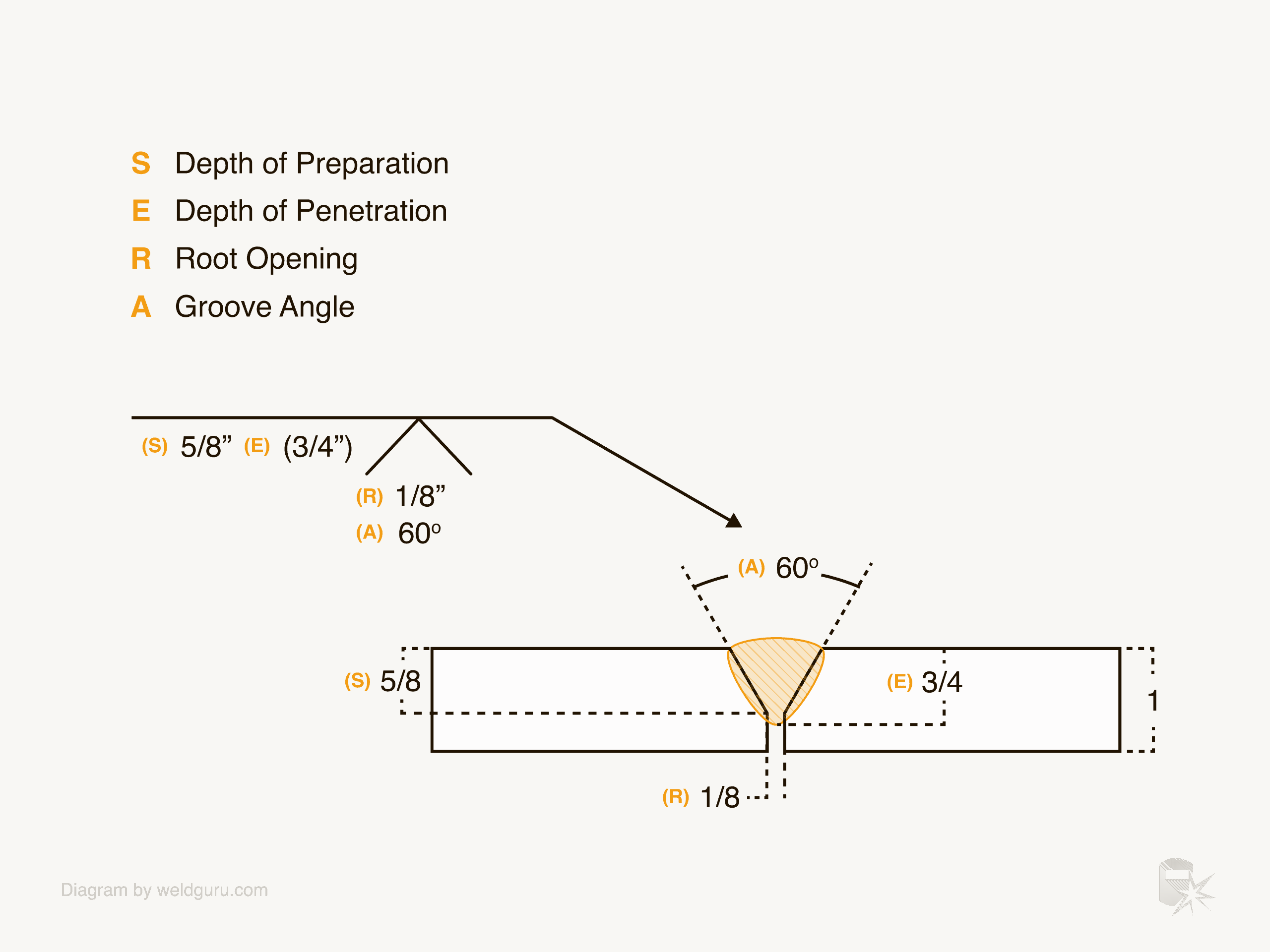
Credit: weldguru.com
Does Groove Angle Affect Weld Quality?
Yes, the groove angle controls penetration, filler metal use, and risk of defects. The wrong angle can cause lack of fusion, excess weld metal, or distortion.
Can I Use The Same Groove Angle For All Welding Processes?
No. Some welding methods, like TIG, need a wider groove for torch access. Others, like automatic SAW, can use a smaller angle. Always match the angle to the process and code.
Where Can I Find Standard Groove Angles For Different Joints?
You can find them in welding standards like AWS D1.1, ASME IX, and ISO 9692-1. These are often available through professional organizations or official publishers. For example, see Wikipedia’s welding joint page for a summary.
Calculating groove angle is one of the most important skills in welding preparation. It affects cost, safety, and performance. Use the right tools, follow the standard, and always double-check your work. With practice, accurate groove angle calculation becomes second nature, leading to better, safer welds every time.